
Inquiry

Project Review

Machining

Quality Control

Pass/Fail

Delivery
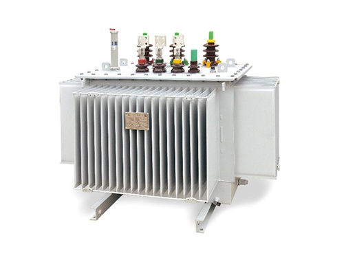
Principle of Amorphous Alloy Transformer
Amorphous alloy transformers are energysaving power transformers that use amorphous alloy materials as the core, replacing the traditional silicon steel sheet core. Their core working principle is based on electromagnetic induction, with the core material's unique properties significantly reducing noload loss, making them more energyefficient than conventional transformers.

1. Core Material Characteristics of Amorphous Alloy
The core is the core component of the transformer, responsible for guiding the magnetic flux generated by the primary winding. The key difference between amorphous alloy and traditional silicon steel sheets lies in its atomic structure and magnetic properties:
| Performance Index | Amorphous Alloy | Silicon Steel Sheet |
|---|---|---|
| Atomic Structure | Non-crystalline, disordered arrangement of atoms | Crystalline, regular arrangement of atoms |
| Magnetic Permeability | High (especially at low magnetic induction intensity) | Moderate |
| Coercivity | Extremely low | Moderate |
| No-load Loss | 70%–80% lower than silicon steel sheets of the same grade | Higher |
| Saturation Magnetic Induction Intensity | Relatively low (1.5–1.6T) | Higher (2.0T for oriented silicon steel) |
Core Advantages
Low coercivity: The amorphous alloy's disordered atomic structure reduces the resistance to magnetic domain rotation and displacement during magnetization and demagnetization, thus minimizing hysteresis loss (the main component of transformer noload loss).
High magnetic permeability: It can effectively guide magnetic flux under low excitation current, reducing the excitation current of the primary winding and further lowering noload loss.
2. Electromagnetic Induction Principle (Consistent with Traditional Transformers)
Amorphous alloy transformers follow the basic law of electromagnetic induction, and their working process is divided into two stages:
2.1 Magnetic Flux Generation by Primary Winding
When alternating current passes through the primary winding, an alternating magnetic flux $\Phi$ is generated in the amorphous alloy core according to Ampere's Circuital Law:
$$N_1I_1 = Hl$$
Where:
$N_1$ = Number of turns of the primary winding
$I_1$ = Alternating current of the primary winding
$H$ = Magnetic field strength of the core
$l$ = Average magnetic path length of the core
2.2 Induced Electromotive Force in Secondary Winding
The alternating magnetic flux passes through the secondary winding, and according to Faraday's Law of Electromagnetic Induction, an induced electromotive force (EMF) is generated in the secondary winding:
$$E_2 = 4.44fN_2\Phi_m$$
Where:
$E_2$ = Induced EMF of the secondary winding
$f$ = Frequency of the alternating current (50Hz or 60Hz)
$N_2$ = Number of turns of the secondary winding
$\Phi_m$ = Maximum magnetic flux of the core
The voltage transformation ratio of the transformer is determined by the turn ratio of the primary and secondary windings:
$$\frac{U_1}{U_2} \approx \frac{N_1}{N_2}$$
Where $U_1$ and $U_2$ are the rated voltages of the primary and secondary windings, respectively.
3. Key Design Principles for EnergySaving Performance
The energysaving advantage of amorphous alloy transformers is mainly reflected in the reduction of noload loss, and its design must address the material's characteristics:
3.1 Matching Magnetic Induction Intensity
Since the saturation magnetic induction intensity of amorphous alloy is lower than that of silicon steel sheets, the design magnetic induction intensity $B_m$ of the core is usually controlled at 1.3–1.4T (while oriented silicon steel can reach 1.7–1.8T). Excessive $B_m$ will cause magnetic saturation, leading to a sharp increase in excitation current and loss.
3.2 Core Structure Design
Strip winding structure: Amorphous alloy strips are thin (typically 0.02–0.03mm) and brittle, so they are wound into a toroidal or rectangular core instead of being laminated like silicon steel sheets. This structure reduces air gaps in the magnetic path and improves magnetic permeability.
Lowstress assembly: Amorphous alloy is sensitive to mechanical stress. Stress will increase its coercivity and loss, so the core clamping force must be precisely controlled during assembly to avoid deformation.
3.3 Reduction of Eddy Current Loss
Although the main energysaving factor is low hysteresis loss, eddy current loss (the other component of noload loss) is also controlled by:
Using ultrathin amorphous alloy strips to shorten the eddy current path.
Coating an insulating layer on the surface of the strips to isolate the strips from each other and prevent eddy current circulation between strips.
4. Limitations and Application Notes
The performance characteristics of amorphous alloy materials also bring certain limitations to the transformer:
1. Low mechanical strength: Amorphous alloy is brittle and easy to crack under vibration or impact, so it is not suitable for highvibration scenarios (unless special vibration reduction measures are taken).
2. Sensitive to temperature: Its magnetic properties deteriorate when the temperature exceeds 120°C, so the operating temperature of the core must be strictly controlled.
3. Higher cost: The price of amorphous alloy materials is higher than that of silicon steel sheets, but the cost can be recovered through longterm energysaving benefits.

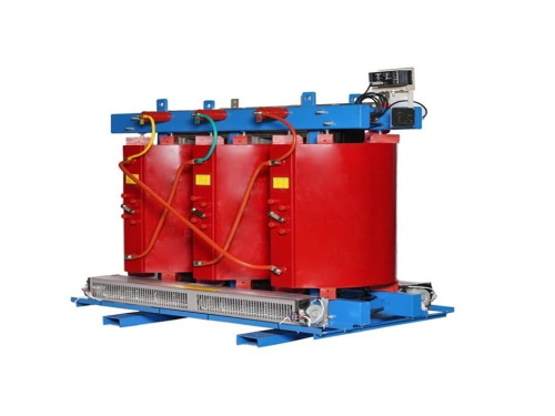
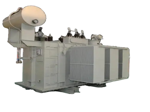
The main products include oil immersed transformers, dry-type transformers, power transformers, amorphous alloy transformers, mining transformers, box type substations, high and low voltage switchgear and supporting products
Add: South Head of Mount Huangshan Road, Liaocheng Development Zone, Shandong, China
Email:derun@drtransformer.com
Tel: +86 13706354419