
Inquiry

Project Review

Machining

Quality Control

Pass/Fail

Delivery
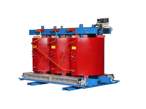
Loss Calculation of DryType Transformers (DryType Transformer Loss Calculation)
Drytype transformer losses are core to energy efficiency evaluation, equipment selection, and operational cost control. They mainly consist of noload loss (iron loss) and load loss (copper loss), with additional considerations for stray loss and dielectric loss (negligible in most engineering scenarios). Below is a detailed breakdown of calculation methods, influencing factors, and practical application guidelines:

1. Classification of DryType Transformer Losses
1.1 NoLoad Loss (Iron Loss, \( P_0 \))
Definition: Losses generated when the transformer is energized at rated voltage (secondary opencircuited), primarily caused by magnetic hysteresis and eddy currents in the core (silicon steel sheet). It is approximately constant during operation (independent of load current, only related to voltage and frequency).
Composition:
Hysteresis loss (\( P_h \)): Energy loss due to repeated magnetization/demagnetization of the core material.
Eddy current loss (\( P_e \)): Induced currents in the core (conductive material) that circulate and generate heat.
Calculation Formula:
P_0 = P_h + P_e = k_h f B_m^{n} G + k_e f^2 B_m^2 d^2 G
Where:
\( k_h \): Hysteresis loss coefficient (related to core material, e.g., silicon steel grade).
\( k_e \): Eddy current loss coefficient (related to core material and manufacturing process).
\( f \): Power frequency (Hz, 50 Hz in China, 60 Hz in some countries).
\( B_m \): Maximum magnetic flux density in the core (T, typically 1.4–1.7 T for drytype transformers).
\( n \): Hysteresis exponent (2–2.5 for silicon steel sheets).
\( d \): Thickness of core laminations (mm, 0.27–0.35 mm for lowloss silicon steel).
\( G \): Mass of the core (kg).
Practical Simplification: For engineering applications, noload loss is directly provided in the transformer’s nameplate or technical manual (tested under rated voltage and frequency). For example, a 1000 kVA drytype transformer may have a nameplate \( P_0 = 1.8 \, \text{kW} \).
1.2 Load Loss (Copper Loss, \( P_k \))
Definition: Losses generated in the windings (copper or aluminum) when the transformer carries load current, primarily due to the resistance of the windings (Joule loss). It is proportional to the square of the load current (or load factor) and varies with operating conditions.
Composition:
Joule loss (\( I^2 R \)): Main component, caused by current passing through winding resistance.
Skin effect loss: Current concentrates on the surface of conductor strands at high frequencies, increasing effective resistance.
Proximity effect loss: Mutual induction between adjacent conductor strands generates eddy currents, increasing loss.
Calculation Formula:
1. Rated load loss (\( P_{kN} \)): Loss at rated current (provided on the nameplate, tested at 75°C for copper windings, 115°C for aluminum windings).
2. Load loss at actual load (\( P_k \)):
P_k = P_{kN} \times \left( \frac{S}{S_N} \right)^2 \times \frac{R_{\theta}}{R_{75^\circ}}
Where:
\( S \): Actual operating apparent power (kVA).
\( S_N \): Rated apparent power (kVA).
\( \frac{S}{S_N} = \beta \): Load factor (0 ≤ β ≤ 1, or >1 for overload).
\( R_{\theta} \): Winding resistance at actual operating temperature (Ω).
\( R_{75^\circ} \): Winding resistance at rated test temperature (75°C for copper, Ω).
Temperature Correction Coefficient:
For copper windings (temperature coefficient \( \alpha_20 = 0.00393 \, ^\circ\text{C}^{1} \)):
\frac{R_{\theta}}{R_{75^\circ}} = \frac{234.5 + \theta}{234.5 + 75} = \frac{234.5 + \theta}{309.5}
For aluminum windings (temperature coefficient \( \alpha_20 = 0.00403 \, ^\circ\text{C}^{1} \)):
\frac{R_{\theta}}{R_{75^\circ}} = \frac{228 + \theta}{228 + 75} = \frac{228 + \theta}{303}
\( \theta \): Actual operating temperature of the winding (°C, typically 80–120°C for drytype transformers, measured by thermocouple or infrared).
Example: A 1000 kVA drytype transformer with \( P_{kN} = 10 \, \text{kW} \) (copper windings) operates at 80% load (\( \beta = 0.8 \)) and winding temperature \( \theta = 90^\circ\text{C} \):
\frac{R_{90^\circ}}{R_{75^\circ}} = \frac{234.5 + 90}{309.5} \approx 1.05
P_k = 10 \times 0.8^2 \times 1.05 = 6.72 \, \text{kW}
1.3 Stray Loss (\( P_s \))
Definition: Losses caused by leakage flux (from windings) inducing eddy currents in structural parts (e.g., core clamps, tank, busbars). It is typically 2–5% of rated load loss for drytype transformers (negligible in basic calculations but considered in highprecision energy efficiency analysis).
Simplified Calculation:
P_s \approx 0.03 \times P_{kN} \times \beta^2
1.4 Total Loss (\( P_{\text{total}} \))
Formula:
P_{\text{total}} = P_0 + P_k + P_s \approx P_0 + P_{kN} \times \beta^2 \times \frac{R_{\theta}}{R_{75^\circ}}
Note: For general engineering calculations, stray loss can be omitted if not specified, and total loss is approximated as \( P_0 + P_k \).
2. Key Influencing Factors
2.1 NoLoad Loss Influencers
Core material: Highgrade silicon steel sheets (e.g., 35W250, 30W190) have lower hysteresis/eddy current losses.
Core structure: Reduced air gaps, optimized lamination stacking, and annealing processes minimize loss.
Rated voltage/frequency: Overvoltage operation (e.g., 110% rated voltage) significantly increases noload loss (proportional to \( V^2 \)).
2.2 Load Loss Influencers
Winding material: Copper windings have lower resistance than aluminum (copper loss ≈ 60–70% of aluminum for the same capacity).
Conductor crosssection: Larger crosssections reduce resistance but increase cost; multistrand conductors mitigate skin/proximity effects.
Load factor: Loss increases with the square of load current (overload operation drastically raises load loss and winding temperature).
Operating temperature: Higher temperature increases winding resistance (e.g., copper resistance rises by ~39% when temperature increases from 75°C to 120°C).
3. Practical Application Scenarios
3.1 Energy Efficiency Evaluation
Transformer efficiency (\( \eta \)) is calculated as:
\eta = \left( 1 \frac{P_{\text{total}}}{S \cos\phi + P_{\text{total}}} \right) \times 100\%
Where \( \cos\phi \) is the load power factor (typically 0.8–0.95 for industrial loads).
Maximum efficiency occurs when \( P_0 = P_k \) (load factor \( \beta_{\text{max}\eta} = \sqrt{\frac{P_0}{P_{kN}}} \)), usually at 40–60% rated load for drytype transformers.
3.2 Sizing and Selection
For continuous fullload operation: Prioritize low \( P_{kN} \) (low copper loss) to reduce operational costs.
For intermittent load or lightload operation (e.g., standby power supply): Prioritize low \( P_0 \) (low iron loss) to minimize noload energy consumption.
3.3 Operational Cost Calculation
Annual energy loss (\( E_{\text{annual}} \)):
E_{\text{annual}} = P_0 \times 8760 + P_{kN} \times \frac{R_{\theta}}{R_{75^\circ}} \times 8760 \times \beta_{\text{avg}}^2
Where \( \beta_{\text{avg}} \) is the average load factor over a year (e.g., 0.6 for general industrial transformers).
4. Notes for Calculation
1. Nameplate Data Priority: Use rated noload loss (\( P_0 \)) and rated load loss (\( P_{kN} \)) from the manufacturer’s nameplate or technical manual (tested under standard conditions) for accuracy.
2. Temperature Correction: For transformers operating at temperatures significantly different from 75°C, correct the winding resistance to avoid calculation errors.
3. Overload Considerations: Overload (β > 1) leads to exponential load loss growth; ensure compliance with temperature limits (e.g., 155°C for Fclass insulation, 180°C for Hclass).
4. Material Distinction: Confirm whether windings are copper or aluminum, as this affects resistance and temperature correction coefficients.
Summary
Drytype transformer loss calculation focuses on noload loss (fixed) and load loss (variable with load). For engineering practice, prioritize nameplate data, apply load factor and temperature corrections, and consider energy efficiency goals for equipment selection. Accurate loss calculation helps optimize operational costs, prevent overheating, and extend transformer service life. For highprecision requirements (e.g., energysaving audits), include stray loss and consult detailed manufacturer test reports.

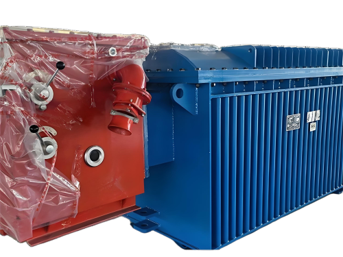
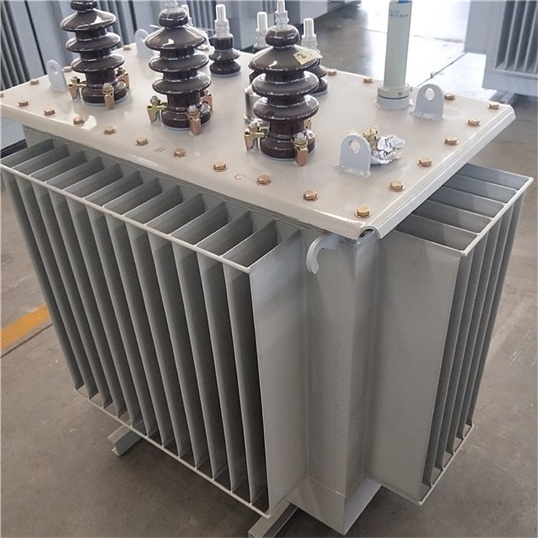
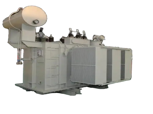
The main products include oil immersed transformers, dry-type transformers, power transformers, amorphous alloy transformers, mining transformers, box type substations, high and low voltage switchgear and supporting products
Add: South Head of Mount Huangshan Road, Liaocheng Development Zone, Shandong, China
Email:derun@drtransformer.com
Tel: +86 13706354419