
Inquiry

Project Review

Machining

Quality Control

Pass/Fail

Delivery
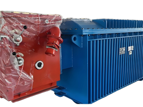
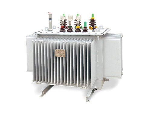
Oilimmersed transformers are widely used in power transmission and distribution systems. Their design integrates electromagnetic conversion, insulation, cooling, and protection functions, with each component working together to ensure stable voltage transformation and safe operation. Below is a detailed breakdown of their main components, categorized by core function:

1. Core Components (Electromagnetic Conversion Core)
The core and windings form the "heart" of the transformer, responsible for realizing the electromagnetic induction principle (the core provides a magnetic circuit, and the windings conduct electrical energy).
1.1 Transformer Core
Material: Made of highquality coldrolled silicon steel sheets (thickness 0.3–0.5 mm) with high magnetic permeability and low iron loss. Silicon steel reduces eddy current and hysteresis losses (the main source of noload losses).
Structure: Adopts a laminated structure (sheets stacked and bonded with insulating paint between layers) to minimize eddy current circulation. Common core shapes include "core type" (windings surround the core column) and "shell type" (core wraps around the windings); coretype is more widely used in oilimmersed transformers.
Function: Provide a lowreluctance magnetic circuit for the alternating magnetic flux generated by the primary winding, ensuring efficient energy transfer between primary and secondary windings.
1.2 Windings (Coils)
Material: Conductors are typically highpurity copper (T2 copper) or aluminum (for costsensitive scenarios). Copper has lower resistivity and better heat resistance, making it suitable for highpower or highvoltage transformers.
Structure: Divided into highvoltage (HV) windings and lowvoltage (LV) windings, both wound around the core column. To reduce leakage flux and losses:
LV windings are usually placed closer to the core (lower insulation requirements, saving space).
HV windings are wrapped around the LV windings (requires thicker insulation to withstand high voltage).
Winding Methods: Common types include layer winding (for lowvoltage, smallcapacity transformers) and disc winding (for highvoltage, largecapacity transformers, with better heat dissipation and mechanical strength).
Function: Convert voltage through the turns ratio (HV winding has more turns, LV winding has fewer turns). The primary winding receives AC power and generates magnetic flux; the secondary winding induces an electromotive force (EMF) from the magnetic flux to output voltage.
2. Insulating Oil (Liquid Insulation & Cooling Medium)
Insulating oil is a unique and critical component of oilimmersed transformers, serving three core roles: insulation, cooling, and arc suppression.
Common Types:
Mineral insulating oil: Derived from petroleum refining, lowcost and widely used (e.g., 25 transformer oil for general climates, 45 for cold regions).
Synthetic insulating oil: (e.g., alkylbenzene oil, silicone oil) with higher fire resistance and environmental friendliness, used in scenarios with strict fire safety requirements (e.g., indoor or urban transformers).
Key Performance Indicators:
Dielectric strength: ≥35 kV/2.5 mm (ability to resist breakdown under high voltage).
Viscosity: Low viscosity ensures good fluidity for heat transfer.
Flash point: ≥135°C (prevents ignition under high temperature).
Water content: ≤10 ppm (moisture severely reduces insulation performance, leading to breakdown).
Function:
Fill gaps between windings, core, and tank to enhance insulation (insulating oil has higher dielectric strength than air).
Absorb heat generated by windings and core during operation, then transfer it to the tank or cooling system for dissipation.
Suppress arcs if internal faults (e.g., short circuits) occur, reducing fault expansion.
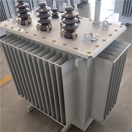
3. Tank & Accessories (Structural Support & Sealing)
The tank is the "outer shell" of the transformer, responsible for containing the core, windings, and insulating oil, while protecting internal components from external environmental damage.
3.1 Transformer Tank
Material: Made of thick lowcarbon steel plates (3–8 mm), welded into a sealed rectangular or cylindrical structure. For largecapacity transformers, the tank may have reinforcing ribs to improve mechanical strength (resisting vacuum during oil filling or pressure during faults).
Sealing Performance: Flanges (e.g., tank cover, bushing interfaces) use nitrile rubber or fluorine rubber gaskets to prevent oil leakage (a common failure point; modern designs adopt "hermetic tanks" for maintenancefree operation).
Function: Provide a closed space for insulating oil, isolate internal components from dust, moisture, and external impacts, and serve as a heat dissipation surface (the outer wall transfers heat to the air).
3.2 Tank Accessories
Oil level gauge: A transparent tube or floattype device to monitor the oil level (low oil level indicates leakage, high oil level may be caused by overheating expansion).
Oil drain valve: Located at the bottom of the tank for oil replacement, sampling, or drainage during maintenance.
Manhole: A largediameter flange opening on the tank side for personnel to enter and inspect internal components (only for largecapacity transformers).
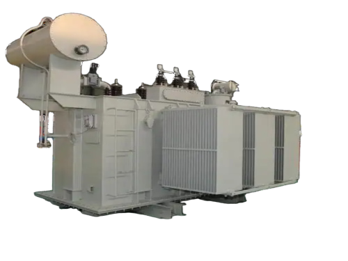
Conservator (Oil Expansion Tank):
A small tank connected to the top of the main tank via a pipeline, used to compensate for oil volume changes caused by temperature fluctuations (oil expands when heated, flows into the conservator; contracts when cooled, flows back).
The conservator is equipped with a breathing valve (or desiccant breather) to filter moisture and dust when the tank "breathes" (prevents oil oxidation and moisture absorption).
4. Cooling System (Heat Dissipation)
Transformers generate heat during operation (from copper loss in windings and iron loss in the core). The cooling system ensures the oil temperature does not exceed the rated limit (usually ≤65°C temperature rise for top oil), avoiding insulation aging or breakdown. Common cooling methods for oilimmersed transformers include:
| Cooling Method | Abbreviation | Working Principle | Applicable Scenarios |
|---|---|---|---|
| Natural Oil Circulation + Natural Air Cooling | ONAN | Heat from windings/core heats oil → hot oil rises to the tank top → heat is transferred to the tank wall and dissipated into the air via natural convection → cold oil sinks to the bottom and circulates. | Small-capacity transformers (≤1000 kVA), low-load density areas. |
| Natural Oil Circulation + Forced Air Cooling | ONAF | Based on ONAN; fans are installed on the tank wall (or radiators) to blow air over the heat dissipation surface, accelerating heat transfer. | Medium-capacity transformers (1000–10,000 kVA), areas with moderate ambient temperatures. |
| Forced Oil Circulation + Forced Air Cooling | OFAF | A 油泵 (oil pump) forces oil to circulate through internal coolers (radiators or oil coolers); fans blow air over the coolers to enhance heat dissipation. | Large-capacity transformers (>10,000 kVA), high-voltage grids (e.g., 220 kV, 500 kV). |
| Forced Oil Circulation + Forced Water Cooling | ODAF | Similar to OFAF, but coolers use circulating water (instead of air) to absorb heat from oil; suitable for high-heat environments (e.g., tropical regions, indoor installations). | Large-capacity transformers in high-temperature or water-abundant areas. |
5. Protection Devices (Safe Operation Guarantee)
To prevent damage from internal faults (e.g., short circuits, insulation breakdown) or external factors (e.g., overvoltage, overheating), oilimmersed transformers are equipped with multiple protection devices:
5.1 Gas Relay (Buchholz Relay)
Installed in the pipeline between the main tank and conservator, the most important internal fault protection device.
Working Principle:
Light gas action: When minor faults (e.g., oil aging, slight leakage) generate small amounts of gas, gas accumulates in the relay, lifting a float and triggering an alarm (no power cutoff).
Heavy gas action: When severe faults (e.g., winding short circuit, core burnout) generate a large amount of gas or cause oil surges, the gas/oil flow impacts a baffle, triggering a trip signal to cut off the transformer’s power supply.
5.2 Pressure Relief Valve (Safety Valve)
Mounted on the tank top, used to release excessive pressure inside the tank. If a severe fault causes oil to decompose rapidly (generating large amounts of gas), the tank pressure rises sharply; the valve opens to release pressure, preventing tank explosion. After pressure drops, the valve closes automatically to avoid oil leakage.
5.3 Temperature Monitoring Device
Top oil temperature gauge: Measures the temperature of the oil at the tank top (the highest oil temperature point), with alarm and trip functions (e.g., alarm at 80°C, trip at 95°C).
Winding temperature indicator: Uses a "thermal simulation" method to indirectly measure winding temperature (windings are hotter than oil), preventing insulation damage from overheating.
5.4 Lightning Arrester (Surge Arrester)
Installed at the highvoltage bushing terminal, used to protect the transformer from transient overvoltage (e.g., lightning strikes, switch operation surges). It diverts overvoltage current to the ground, limiting the voltage across the transformer windings to a safe range.
6. Other Auxiliary Components
6.1 Bushings
Insulating devices that connect the internal windings to external power lines (installed on the tank top). They isolate high voltage from the grounded tank and prevent oil leakage.
Types:油纸绝缘 bushings (for high voltage, ≤500 kV) and composite insulation bushings (for medium voltage, ≥110 kV, lighter and more resistant to pollution).
6.2 Tap Changer
Used to adjust the transformer’s output voltage (compensating for grid voltage fluctuations). It changes the number of turns of the highvoltage winding:
Offload tap changer: Adjusted only when the transformer is deenergized (simple structure, low cost, used in lowvoltage distribution transformers).
Onload tap changer (OLTC): Adjusted while the transformer is in operation (complex structure, high cost, used in highvoltage power transformers requiring stable voltage output).
6.3 Grounding Device
The tank and core are grounded (via a grounding bolt) to prevent electric shock from induced voltage on the tank and ensure stable magnetic circuit operation (core grounding avoids circulating current).
Summary of Component Collaboration
The oilimmersed transformer’s components form a closed system: the core and windings realize voltage transformation; insulating oil provides insulation and transfers heat; the cooling system dissipates heat to maintain temperature; the tank and protection devices ensure structural integrity and fault safety; and auxiliary components (bushings, tap changers) enable connection to the grid and voltage regulation. This integration ensures the transformer operates efficiently, safely, and reliably in power systems.

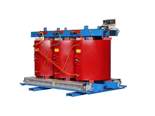
The main products include oil immersed transformers, dry-type transformers, power transformers, amorphous alloy transformers, mining transformers, box type substations, high and low voltage switchgear and supporting products
Add: South Head of Mount Huangshan Road, Liaocheng Development Zone, Shandong, China
Email:derun@drtransformer.com
Tel: +86 13706354419