
Inquiry

Project Review

Machining

Quality Control

Pass/Fail

Delivery
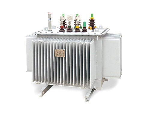
Configuring a dry-type transformer requires systematic matching of its technical parameters, structural design, and accessory functions to the actual application scenario (e.g., industrial plants, data centers, commercial buildings) while ensuring compliance with safety standards, energy efficiency, and long-term reliability. Below is a step-by-step guide to configuration, covering core requirements, key parameters, structural options, and practical considerations.
1. Pre-Configuration: Clarify Core Requirements
Before selecting parameters, first define the application context to avoid mismatches. Key requirements to confirm include:
| Requirement Category | Key Details to Confirm |
|---|---|
| Application Scenario | - Indoor/outdoor installation (affects enclosure IP rating). - Industry type: e.g., data centers (high load density, harmonic sensitivity), factories (heavy-duty, dusty), commercial buildings (low noise). |
| Load Characteristics | - Rated load: Total power of downstream equipment (add 10–20% margin for future expansion). - Load type: Linear (e.g., motors) or non-linear (e.g., inverters, UPS—requires harmonic tolerance). - Load variation: Continuous (e.g., data centers) or intermittent (e.g., manufacturing—affects overload capacity). |
| Grid Parameters | - Input voltage (primary side): e.g., 10kV, 6kV (medium voltage) or 380V (low voltage). - Output voltage (secondary side): e.g., 400V/230V (three-phase/single-phase for distribution). - Frequency: 50Hz (global) or 60Hz (North America, Japan). |
| Environmental Conditions | - Ambient temperature: e.g., -20°C to +40°C (standard) or extreme temperatures (requires insulation adaptation). - Humidity: ≤90% RH (non-condensing; high humidity needs dehumidifiers). - Altitude: ≤1000m (above 1000m requires derating due to reduced air insulation). |
| Safety & Compliance | - Local standards: e.g., IEC (Europe), ANSI (US), GB (China), UL (North America). - Special requirements: Fire resistance (e.g., for high-rises), explosion protection (e.g., chemical plants). |
2. Core Technical Parameter Configuration
These parameters directly determine the transformer’s performance and compatibility with the power system.
2.1 Rated Capacity (kVA)
- Selection principle: Match the total active power of downstream loads, considering power factor (PF) and expansion margin.
Formula: `Rated capacity (kVA) = Total active load (kW) / Power factor (PF)`
- Example: If downstream equipment totals 800kW with PF=0.8, select a 1000kVA transformer (800/0.8=1000).
- Margin: Add 10–20% for future load growth (e.g., 800kW load → 1250kVA transformer for expansion).
- Derating factors: Reduce capacity if operating in extreme conditions:
- Altitude >1000m: Derate by 1% for every 100m increase.
- Ambient temperature >40°C: Derate by 2.5% for every 1°C increase.
2.2 Voltage Ratio & Tap Changer
- Voltage ratio: Determined by primary (input) and secondary (output) voltages.
Example: 10kV (primary) → 0.4kV (secondary) → Voltage ratio = 10/0.4 = 25:1.
- Tap changer: Compensates for grid voltage fluctuations (e.g., ±5% of rated voltage).
- On-load tap changer (OLTC): Adjusts voltage without power interruption (for critical loads like data centers).
- Off-load tap changer (OLTC): Requires power shutdown (for non-critical loads like general factories).
2.3 Connection Group (Vector Group)
Defines the phase relationship between primary and secondary windings, critical for harmonic suppression and system grounding. Common options:
| Connection Group | Primary/Secondary Winding | Key Advantages | Typical Applications |
|---|---|---|---|
| Dyn11 | Delta (D) / Star (yn) | - Strong harmonic tolerance (suppresses 3rd harmonics). - Stable neutral point for single-phase loads. | Data centers, commercial buildings, UPS systems. |
| Yyn0 | Star (Y) / Star (yn) | - Simple structure, low cost. - Suitable for linear loads. | General factories (motors), residential areas. |
| Dd0 | Delta (D) / Delta (D) | - High short-circuit resistance. - No neutral point. | Three-phase industrial loads (e.g., pumps, fans). |
2.4 Impedance Voltage (Uk%)
- Definition: Voltage drop percentage at rated current, reflecting short-circuit resistance and load capacity.
- Selection:
- Low Uk% (4–6%): Smaller voltage drop, better for sensitive loads (e.g., precision instruments).
- High Uk% (6–8%): Stronger short-circuit withstand capacity, better for industrial loads with frequent startups (e.g., motors).
2.5 Insulation Class & Temperature Rise
Dry-type transformers use class F or class H insulation (based on IEC 60076-11), which defines maximum allowable temperatures:
| Insulation Class | Max Allowable Temperature | Temperature Rise Limit (over 40°C ambient) | Typical Applications |
|---|---|---|---|
| Class F | 155°C | 100K (140°C operating temp) | General factories, commercial buildings. |
| Class H | 180°C | 125K (165°C operating temp) | High-temperature environments (e.g., steel plants, data centers). |
3. Structural & Accessory Configuration
3.1 Cooling System
Dry-type transformers rely on air cooling (no oil, fire-safe). Two main types:
| Cooling Method | Code (IEC) | Working Principle | Capacity Range | Application Scenario |
|---|---|---|---|---|
| Natural Air Cooling (NAC) | AN | Heat dissipation via convection (no fans). | ≤800kVA | Low-load, low-temperature environments (e.g., offices). |
| Forced Air Cooling (FAC) | AF | Fans activate when temp >80°C (auto-control). | ≥1000kVA | High-load, high-temperature environments (e.g., data centers, factories). |
3.2 Enclosure Design
Enclosures protect the transformer from dust, moisture, and physical damage. Select based on installation environment:
| IP Rating | Protection Level | Installation Scenario |
|---|---|---|
| IP20 | Protection against solid objects >12mm (e.g., fingers). No water protection. | Indoor, clean environments (e.g., data centers, control rooms). |
| IP30 | Protection against solid objects >2.5mm. No water protection. | Indoor, slightly dusty environments (e.g., factories). |
| IP54 | Protection against dust (limited ingress) and splashing water (all directions). | Semi-outdoor (e.g., covered parking lots, outdoor switchgear rooms). |
| IP65 | Full dust protection and protection against low-pressure water jets. | Outdoor (e.g., utility poles, open-air industrial sites). |
3.3 Protection & Monitoring Accessories
Critical for safety and predictive maintenance:
| Accessory Type | Key Functions |
|---|---|
| Temperature Protection | - PT100 temperature sensors (monitor winding/core temp). - Thermal overload relay (cuts power if temp exceeds limit). |
| Electrical Protection | - Overcurrent circuit breakers (OCPD). - Surge arresters (protect against lightning/voltage spikes). - Ground fault protection (detect leakage current). |
| Smart Monitoring | - Digital meters (measure voltage, current, power factor). - Remote communication (Modbus, IEC 61850) for real-time data transmission to SCADA systems. - Alarm systems (audio/visual alerts for overtemp, overload). |
| Noise Reduction | - Low-loss amorphous alloy core (reduces magnetic noise). - Damping pads (reduce vibration noise). - Soundproof enclosures (for quiet areas like hospitals, residential buildings—target noise ≤50dB at 1m). |
4. Compliance & Standard Validation
Ensure the configured transformer meets local and international standards to avoid safety risks and operational failures:
| Region | Core Standards |
|---|---|
| Global | IEC 60076-11 (Dry-type transformers), IEC 61558 (Safety of power transformers). |
| North America | ANSI C57.12.01 (Distribution transformers), UL 1561 (Dry-type transformers). |
| China | GB 1094.11 (Dry-type transformers), GB 20052 (Energy efficiency for transformers). |
5. Practical Configuration Example
Scenario: 1250kVA Dry-Type Transformer for a Data Center
| Parameter | Configuration Choice |
|---|---|
| Rated Capacity | 1250kVA (supports 1000kW load at PF=0.8 + 20% expansion margin). |
| Voltage Ratio | 10kV/0.4kV (matches medium-voltage grid and low-voltage IT equipment). |
| Connection Group | Dyn11 (suppresses 3rd harmonics from UPS/inverters). |
| Impedance Voltage | 6% (balances voltage stability and short-circuit protection). |
| Insulation Class | Class H (withstands high temps from dense server racks). |
| Cooling System | AF (forced air cooling, 4 fans with 1 standby). |
| Enclosure | IP30 (indoor, dust-proof for data center cleanrooms). |
| Accessories | - PT100 sensors + remote temperature monitoring. - OLTC (on-load tap changer for voltage stabilization). - Surge arresters (protect against grid spikes). |
| Compliance | IEC 60076-11, GB 20052 Class 2. |
6. Common Pitfalls to Avoid
1. Undersizing: Ignoring load expansion margin leads to long-term overload and premature failure.
2. Mismatched Connection Group: Using Yyn0 for non-linear loads (e.g., data centers) causes harmonic accumulation.
3. Neglecting Environmental Adaptation: Using IP20 enclosures in dusty factories leads to insulation degradation.
4. Overlooking Cooling Redundancy: Single-fan AF systems risk overheating if the fan fails.
By following this framework, you can configure a dry-type transformer that balances performance, safety, and cost while meeting the specific needs of your application. For complex scenarios (e.g., high-harmonic loads, extreme environments), consult with transformer manufacturers for custom solutions.

The main products include oil immersed transformers, dry-type transformers, power transformers, amorphous alloy transformers, mining transformers, box type substations, high and low voltage switchgear and supporting products
Add: South Head of Mount Huangshan Road, Liaocheng Development Zone, Shandong, China
Email:derun@drtransformer.com
Tel: +86 13706354419