
Inquiry

Project Review

Machining

Quality Control

Pass/Fail

Delivery
Principle and Key Operating Points for Adjusting the Tap Positions of Amorphous Alloy Transformers

I. Core Principle of Tap Position Adjustment
Amorphous alloy transformers control output voltage precisely by adjusting the number of turns in the high-voltage side winding to modify the turns ratio (K=W2W1=U2U1). The tap position design follows this logic:
Relationship Between Tap Position and Turns:
Higher tap positions correspond to more turns in the high-voltage winding, resulting in lower output voltage.
Lower tap positions correspond to fewer turns in the high-voltage winding, resulting in higher output voltage.Voltage Adjustment Mnemonic: "High to High, Low to Low"
When the output voltage is too high, shift to a higher tap position (e.g., from Position 3 to Position 4) to reduce high-voltage winding turns and lower the output voltage.
When the output voltage is too low, shift to a lower tap position (e.g., from Position 3 to Position 2) to increase high-voltage winding turns and raise the output voltage.II. Tap Position Design and Typical Parameters
1. Number of Tap Positions and Voltage Range
Common distribution transformers feature 3 or 5 tap positions, with each position adjusting voltage by ±5% or ±2.25%. For a 10 kV transformer, a 5-position design is illustrated below:
| Tap Position | High-Voltage Side Voltage | Output Voltage Change (Low-Voltage Side) |
|---|---|---|
| Position 1 | 10,500 V | +5% |
| Position 2 | 10,250 V | +2.5% |
| Position 3 | 10,000 V | Rated Value (400 V) |
| Position 4 | 9,750 V | -2.5% |
| Position 5 | 9,500 V | -5% |
2. Impact of Amorphous Alloy Characteristics on Tap Positions
Low Saturation Flux Density: Amorphous alloy materials typically have a saturation flux density of 1.3–1.35 T, necessitating precise tap adjustments to avoid magnetic saturation.
Sensitivity to Mechanical Stress: The amorphous alloy core is vulnerable to deformation under mechanical stress, which may increase no-load losses. Thus, tap adjustments must prevent core stress.
III. Tap Position Adjustment Procedures
1. Off-Load Tap Changing (Requires Power Disconnection)
Step 1: Disconnect the load, verify voltage absence, and install grounding wires to ensure safety.
Step 2: Remove the tap changer protective cover and move the positioning pin to the neutral position.
Step 3: Adjust the tap position based on output voltage requirements:
For low voltage: Shift to a lower voltage position (e.g., Position 3 → Position 4).
For high voltage: Shift to a higher voltage position (e.g., Position 3 → Position 2).
Step 4: After adjustment, verify the positioning pin is securely fixed.
Step 5: Measure the resistance of the three-phase windings; the resistance difference must not exceed 1.5%. If exceeded, inspect the tap changer contacts.
2. Automatic Voltage Regulation (Requires Automatic Control Equipment)
Adjust tap positions incrementally via an automatic device, with a minimum interval of 90 seconds between positions. Do not skip positions to prevent current surges.
IV. Applications of Tap Position Adjustment
1. Addressing Grid Voltage Fluctuations
When voltage instability occurs due to long transmission distances or peak demand, tap adjustments stabilize the low-voltage side at 400 V, preventing equipment shutdowns.
Case Example: Fujian Zhangping Power Supply Company improved voltage compliance by 12% by setting transformers to Position 3 in summer.
2. Adapting to Load Variations
During peak periods, shift to lower positions (e.g., Position 2 → Position 3) to raise voltage.
During off-peak periods, shift to higher positions (e.g., Position 2 → Position 1) to lower voltage.
Case Example: Hunan Chaling Power Supply Company managed a 30% load surge during the Spring Festival by setting transformers to Position 1.
3. Energy Conservation
Proper tap adjustments reduce line losses: raising voltage during peaks lowers current, while lowering voltage during off-peak periods saves energy.
Case Example: A county reduced line losses from 7.44% to 3.1% and saved $48,000 annually in electricity costs after implementation.
V. Precautions for Tap Position Adjustment
1. Avoid Adjusting Under Overload Conditions
Tap changes are prohibited when the transformer is overloaded, as this may burn out the tap changer.
Case Example: A chemical plant’s tap changer burned out due to overload adjustment, requiring 36 hours for repair.
2. Regular Inspection and Maintenance
Test oil samples after 6 months of operation or 2,000 tap changes.
Perform core inspection after 5,000 tap changes.
Case Example: Inner Mongolia Power Grid identified carbonized insulation paper causing core grounding faults, highlighting the importance of routine checks.
3. Special Requirements for Amorphous Alloy Transformers
Prevent Core Stress: Ensure no external force is applied to the core during tap adjustments to avoid increased no-load losses.
Annealing Treatment: Amorphous alloy core laminations must undergo annealing to achieve optimal low-loss performance.

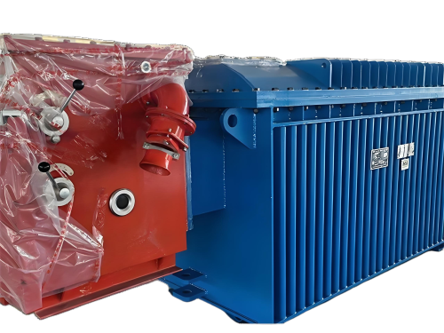
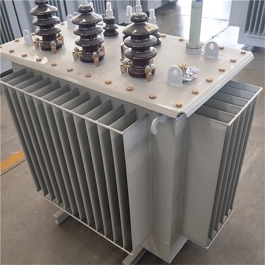
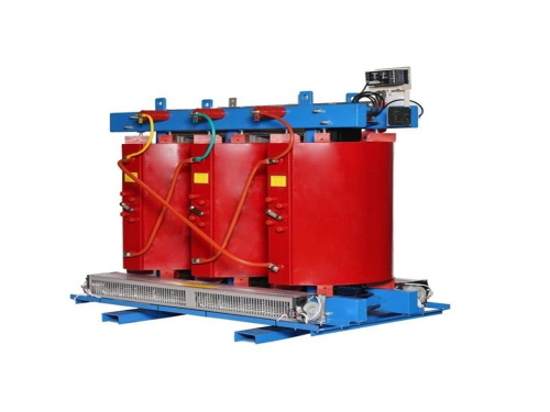
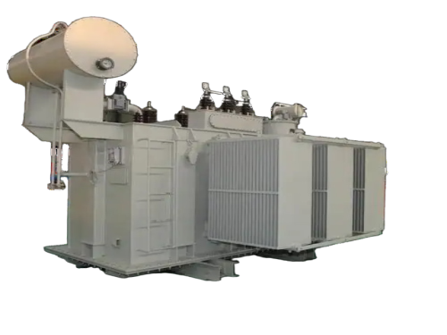
The main products include oil immersed transformers, dry-type transformers, power transformers, amorphous alloy transformers, mining transformers, box type substations, high and low voltage switchgear and supporting products
Add: South Head of Mount Huangshan Road, Liaocheng Development Zone, Shandong, China
Email:derun@drtransformer.com
Tel: +86 13706354419