
Inquiry

Project Review

Machining

Quality Control

Pass/Fail

Delivery
The grounding operation regulations for mining transformers are mainly based on relevant national standards and industry regulations. The following are the specific requirements:

Basic Principles
It is strictly prohibited to directly ground the neutral point of the underground distribution transformer, and it is also prohibited to supply power to the underground from a transformer or generator with a directly grounded neutral point on the ground. However, this does not apply to special transformers dedicated to underground trolley wire locomotive converter equipment.
Each piece of equipment must be directly connected to the grounding network (grounding busbar, auxiliary grounding busbar) with an independent connecting wire. It is prohibited to connect several pieces of equipment in series for grounding, or to connect several grounding parts in series.
Grounding Electrode Requirements
Main Grounding Electrode: According to the "Detailed Rules for the Installation, Inspection, and Measurement of Protective Grounding Devices in Coal Mines", the main grounding electrodes in the main and auxiliary water sumps and the main grounding electrodes in the sub areas shall all be made of steel plates with an area of not less than 0.75m² and a thickness of not less than 5mm.
Local Grounding Electrode: It should be independently buried in places where electrical equipment is installed, such as in electromechanical chambers, substations, power distribution points, cable junction boxes, etc. to strengthen the reliability of the grounding system and ensure that the grounding resistance of the total grounding network does not exceed 2Ω.
Grounding Wire Requirements
The grounding busbar and the auxiliary grounding busbar of the substation shall be made of bare copper wires with a cross section of not less than 50mm², galvanized iron wires with a cross section of not less than 100mm², or galvanized flat steel with a thickness of not less than 4mm and a cross section of not less than 100mm².
The connection between the grounding wire and the grounding busbar (or auxiliary grounding busbar) should preferably be welded. If welding is not possible, a galvanized bolt with a diameter of not less than 10mm and an anti loosening device (spring washer, nut) can be used for tightening connection. The connection part should be tinned or galvanized. When binding with bare copper wires, the binding length along the axial direction of the grounding busbar shall not be less than 100mm.
Transformer Grounding Methods
For the grounding of transformers, the steel belts and lead sheaths of the armored cables on the high and low voltage sides shall be respectively connected to the grounding dedicated screws on the transformer casing with connecting wires. If rubber sheathed cables are used, the grounding core wire of the cable shall be connected to the internal grounding terminal of the inlet and outlet device, and then the grounding screw of the transformer casing shall be connected to the grounding busbar (or auxiliary grounding busbar) with a connecting wire.
Grounding Resistance Measurement
The measurement of the grounding resistance of the underground total grounding network shall be the responsibility of a dedicated person, and it shall be measured at least once every quarter. For newly installed grounding devices, the grounding resistance value shall be measured before they are put into operation, and the measured data must be recorded in the record sheet.
In mines with gas and coal dust explosion hazards, intrinsically safe grounding megohmmeters should be used for grounding resistance measurement.

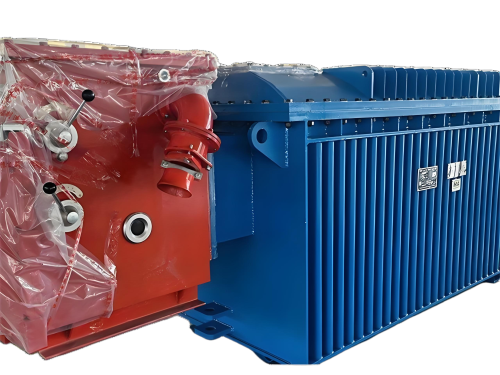
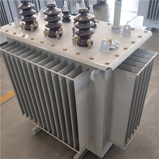
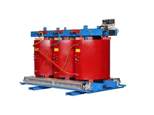
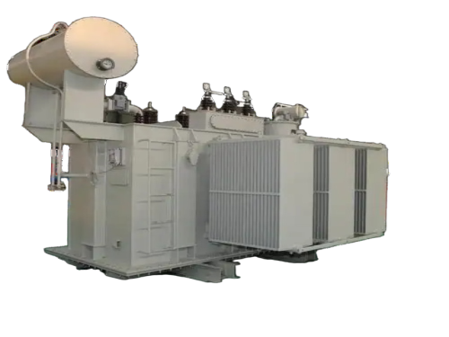
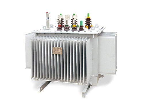
The main products include oil immersed transformers, dry-type transformers, power transformers, amorphous alloy transformers, mining transformers, box type substations, high and low voltage switchgear and supporting products
Add: South Head of Mount Huangshan Road, Liaocheng Development Zone, Shandong, China
Email:derun@drtransformer.com
Tel: +86 13706354419