
Inquiry

Project Review

Machining

Quality Control

Pass/Fail

Delivery
I. Core Calculation Formulas
Basic Impedance Formula
Calculate transformer impedance based on the short-circuit impedance percentage:
ZT=uk%×SN.TU2N2
Where:
ZT = Transformer impedance (Ω);
uk% = Short-circuit impedance percentage (rated value from nameplate or measured value);
U2N = Secondary-side rated voltage (kV);
SN.T = Rated capacity (kVA).
Resistance and Reactance Decomposition
Calculate resistance using short-circuit loss:
RT=ΔPN×SN.T2U2N2
Calculate reactance using the vector relationship between impedance and resistance:
XT=ZT2−RT2
Where ΔPN = Short-circuit loss (kW).

II. Key Parameter Acquisition
Short-Circuit Impedance Percentage (uk%)
Prioritize the value stated on the transformer nameplate;
If unavailable, measure via short-circuit test: Apply a low voltage to the primary side to achieve rated current on the secondary side, then measure the ratio of input voltage to rated voltage.
Rated Capacity and Voltage
Rated capacity SN.T is directly obtained from the nameplate;
Secondary-side rated voltage U2N is determined based on system voltage levels (e.g., 6kV, 10kV).
III. Voltage Level Conversion
High-Voltage Side and Low-Voltage Side Impedance Conversion
When the system voltage differs from the transformer's rated voltage, convert impedance using the square ratio of voltages:
ZActual=(UActualURated)2×ZRated
Example: Converting impedance from a 6000V rated value to a 690V system:
Z690=(6906000)2×Z6000IV. Zero-Sequence Impedance Calculation (Special Scenarios)
Impact of Winding Structure
Three-phase five-limb core structures with D,yn11 winding configurations suppress third harmonics. Their zero-sequence magnetic flux paths differ from positive-sequence paths;
Calculate zero-sequence reactance using finite element methods or the Stanford-MIT method, considering winding spacing and core environment.
Design of Zero-Sequence Protection Components
The zero-sequence reactance value directly influences the selection of zero-sequence protection components, ensuring they can withstand the system's maximum zero-sequence current.
V. Engineering Application Considerations
Short-Circuit Current Calculation
Use impedance values to calculate the secondary-side short-circuit current of the transformer:
Isc=3×(ZT+ZLine)U2N
Requires comprehensive analysis incorporating line impedance.
Parallel Operation Requirements
When multiple transformers operate in parallel, the impedance voltage deviation should be ≤±10% to avoid uneven load distribution.
Compliance with Standards and Specifications
Mining transformers must comply with GB/T 1094 "Power Transformers" standards;
Typical impedance voltage values: 4%-5.5% for 6-10kV class, 6.5%-8% for 35kV class.

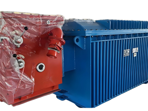
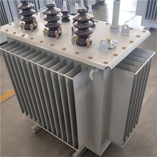
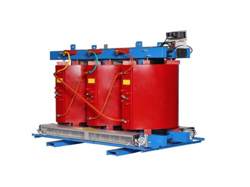
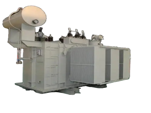
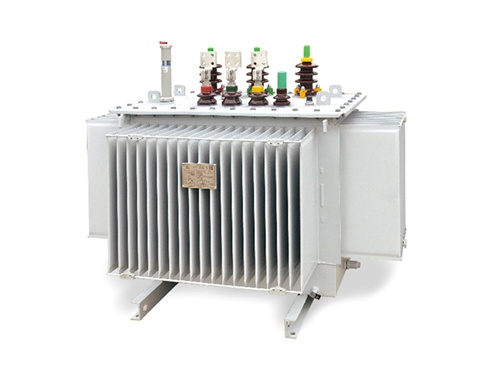
The main products include oil immersed transformers, dry-type transformers, power transformers, amorphous alloy transformers, mining transformers, box type substations, high and low voltage switchgear and supporting products
Add: South Head of Mount Huangshan Road, Liaocheng Development Zone, Shandong, China
Email:derun@drtransformer.com
Tel: +86 13706354419