
Inquiry

Project Review

Machining

Quality Control

Pass/Fail

Delivery
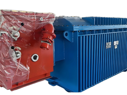
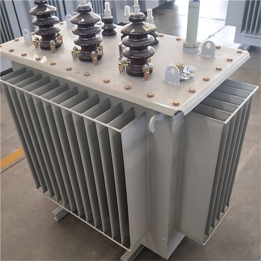
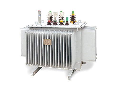
Oil-immersed transformers are among the most widely used power distribution and transmission devices in electrical grids, industrial facilities, and renewable energy projects. Their high efficiency, excellent cooling characteristics, and long operational life make them indispensable for medium- to large-scale power systems. However, because they contain flammable insulating oil, proper installation and safe operation are not merely best practices — they are legal and safety requirements.
This article provides a comprehensive guide to oil-immersed transformer installation standards and safe operation requirements, covering site selection, foundation design, clearances, oil containment, grounding, fire protection, routine inspections, and emergency response.
Choosing the correct installation location is the first step toward safe and reliable transformer operation. The following factors must be considered:
Ventilation: The site must allow natural or forced air circulation to dissipate heat from radiator fins or tank walls. For indoor installations, dedicated ventilation ducts or fans are required.
Drainage: The area must have adequate drainage to prevent water accumulation around the transformer base.
Accessibility: Sufficient space must be provided for maintenance personnel, lifting equipment, and oil handling vehicles.
Separation from combustible materials: The transformer should be installed at least 3 meters away from buildings or combustible structures unless fire barriers are installed.
Indoor installations require a dedicated transformer room with fire-resistant walls (minimum 2-hour fire rating) and self-closing fire doors.
The transformer foundation must support the total weight of the transformer plus oil. Key requirements include:
Concrete base: A reinforced concrete pad with leveling inserts and anchor bolts.
Oil containment pit (bunding): A spill containment area capable of holding 110% of the transformer’s total oil volume. This pit should be lined with oil-resistant coating or stainless steel.
Oil drainage system: Connected to an oil-water separator or collection tank, not directly to storm drains.
Vibration isolation: Rubber pads or spring isolators where vibration transmission must be minimized.
For pole-mounted oil-immersed transformers (typically up to 500 kVA), steel platforms must be securely attached to utility poles with anti-climbing guards.
The table below summarizes minimum recommended clearances according to IEC 61936-1 and IEEE C57.12.00:
| Location | Minimum Clearance |
|---|---|
| Between live parts and ground | 2.0 m (for ≤ 36 kV) |
| Between phases | 1.2 m (for ≤ 36 kV) |
| From transformer to building wall | 1.5 m (maintenance side) |
| Above transformer to ceiling/roof | 3.0 m (indoor) |
| Between multiple transformers | 3.0 m |
For outdoor installations, fences or enclosures must be at least 2.0 m away from live parts and locked to prevent unauthorized access.
Proper grounding is essential for fault protection and lightning surge dissipation. The installation must include:
Two independent ground connections from the transformer tank to the station grounding grid.
Neutral grounding resistor (NGR) or solid grounding depending on system design.
Ground conductor size: Minimum 50 mm² copper or equivalent for distribution transformers.
Ground resistance: Less than 1 Ω for industrial and utility substations.
All non-current-carrying metal parts (tank, radiators, tap changer handle, etc.) must be bonded to the ground busbar.
High-voltage bushings: Must be clean and dry before termination. Stress cones must be installed for shielded cables.
Low-voltage bushings: Use flexible copper or aluminum connectors. Torque values must follow manufacturer specifications.
Cable support: Cables must be supported to prevent mechanical pull on bushings.
Phase identification: Phases L1 (R), L2 (S), L3 (T) must be clearly marked at both ends.
Because the insulating oil is combustible (flash point typically 140–160°C for mineral oil), the following fire protection measures are mandatory in many jurisdictions:
Fire walls: A 2-hour fire-rated concrete wall between transformers and between transformer and building.
Automatic fire suppression: Water mist, foam, or dry chemical systems in indoor substations.
Oil drainage valve: Automatic gravity-operated valve that drains oil to a remote pit in case of rupture.
Fire alarms: Smoke and heat detectors connected to facility fire alarm system.
Outdoor transformers above 10 MVA often require a gravel bed (50–80 mm stone) covering the oil pit to suppress fire propagation.
After mechanical installation, the following tests and checks must be completed:
Insulation resistance test (megger) – primary to secondary, primary to ground, secondary to ground.
Winding resistance measurement – all tap positions.
Transformer turns ratio (TTR) test – verify nameplate ratio.
Oil dielectric strength test – should be ≥ 60 kV for new oil.
Oil dissolved gas analysis (DGA) – baseline record.
Bushing power factor test (for high-voltage units).
Protection relay settings – verify overcurrent, earth fault, and Buchholz relay settings.
Cooling system check – fans and pumps (if fitted) operate correctly.
Only when all tests pass and all safety interlocks are confirmed should the transformer be energized.

Once installed, ongoing safe operation requires a combination of regular monitoring, preventive maintenance, and clear procedures.
Operators should look for:
Oil leaks – around gaskets, bushings, valves, and welds.
Silica gel breather color – pink indicates moisture saturation (replace or regenerate).
Oil level in conservator tank – must be within marked range for current oil temperature.
Unusual noise – humming is normal, but crackling suggests partial discharge.
Temperature indicators – top oil temperature should not exceed 95°C for standard mineral oil (105°C for high-temperature oils).
Damage or corrosion – on tank, radiators, bushings, and nameplate.
Any abnormal condition must be logged and escalated to maintenance personnel.
For critical transformers, continuous online monitoring is recommended for:
Oil temperature (top oil and hotspot)
Winding temperature (simulated or fiber-optic)
Oil level
Dissolved gases (H₂, C₂H₂, CO, C₂H₄) – early fault detection
Load current – avoid prolonged overload beyond nameplate rating
Ambient temperature – affects cooling capacity
Modern transformers can be retrofitted with IoT sensors that send alarms to a central SCADA system.
| Parameter | Frequency | Action Limit |
|---|---|---|
| Dielectric strength | Annually (or after fault) | < 50 kV – reclaim or replace oil |
| Water content | Annually | > 25 ppm – oil drying required |
| Dissolved gas (DGA) | Annually for < 10 MVA; semi-annual for larger | Follow IEEE C57.104 / IEC 60599 |
| Acidity (TAN) | Every 2 years | > 0.2 mg KOH/g – oil regeneration |
| Interfacial tension (IFT) | Every 2 years | < 24 mN/m – oil degradation |
Oil-immersed transformers have a defined nameplate rating (kVA) based on a specified ambient temperature (usually 40°C max). Safe operation requires:
Normal loading: Do not exceed nameplate kVA continuously.
Emergency overload (per IEEE C57.91): Up to 150% for brief periods (e.g., 30 minutes) but only when starting from normal oil temperature and ambient below 30°C.
Load balancing: Avoid phase imbalance exceeding 10% of nominal current.
Repeated overloading accelerates paper insulation aging (thermal life rule: every 8°C above rated reduces life by 50%).
Lockable fence or room door – only authorized electrical personnel.
Warning signs – “Danger – High Voltage”, “Oil-Immersed Transformer – No Open Flames”.
Emergency instructions – posted outside transformer room: shutdown procedure, fire extinguisher location, emergency contact numbers.
Spill kit – absorbent pads, booms, and disposal bags stored near transformer.
A qualified technician should perform:
Torque check of bushing and cable connections.
Bushing cleaning – especially outdoor porcelain types.
Tap changer exercise – move through all positions (if de-energized) to remove oxidation.
Cooling system service – fan motors, bearings, control contactors.
Buchholz relay test – manual float and contact check.
Pressure relief device check – set pressure verification.
Ground resistance measurement – ensure remains below 1 Ω.
If any of the following occurs, de-energize the transformer immediately and notify supervisors:
Buchholz relay trip (gas accumulation or sudden pressure)
Heavy smoke or fire
Major oil spill
Abnormal sound (arcing inside tank)
Rapid temperature rise (> 10°C in 10 minutes under steady load)
For transformer fire:
Disconnect primary and secondary breakers.
If safe, activate fixed fire suppression system.
Do not use water jet directly on oil fire – use foam, CO₂, or dry powder.
Evacuate area and call emergency services.
| Mistake | Consequence |
|---|---|
| Inadequate oil containment pit | Environmental fines and soil contamination |
| Missing or undersized grounding | Electrocution risk, relay misoperation |
| Blocked ventilation ducts | Premature insulation failure due to overheating |
| Bushing surface contamination | Tracking, flashover, and power outage |
| Delayed oil analysis | Undetected internal faults (e.g., arcing, overheating) |
| Bypassing Buchholz relay | Loss of early fault detection |
Proper installation and safe operation of oil-immersed transformers require strict adherence to international standards such as IEC 60076, IEEE C57.12.00, and local electrical codes. From foundation design and grounding to oil monitoring and emergency response, every detail affects the transformer’s reliability, lifespan, and safety. By following the guidelines outlined in this article — including routine inspections, oil analysis, load management, and fire protection — facility owners and electrical engineers can prevent unplanned outages, extend transformer life beyond 30 years, and protect personnel and property.
For assistance with oil-immersed transformer installation, testing, or maintenance, please consult a qualified power engineering firm or transformer manufacturer.

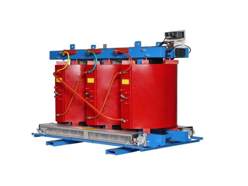
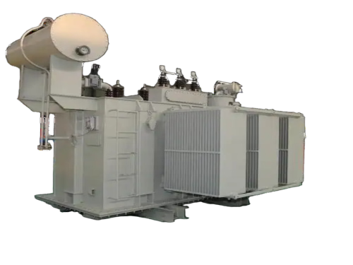
The main products include oil immersed transformers, dry-type transformers, power transformers, amorphous alloy transformers, mining transformers, box type substations, high and low voltage switchgear and supporting products
Add: South Head of Mount Huangshan Road, Liaocheng Development Zone, Shandong, China
Email:derun@drtransformer.com
Tel: +86 13706354419