
Inquiry

Project Review

Machining

Quality Control

Pass/Fail

Delivery
Analysis of Manufacturing Processes for Amorphous Alloy Transformers
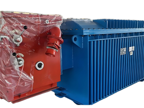
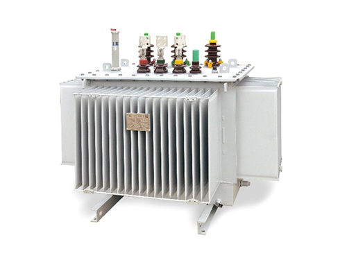
Amorphous alloy transformers utilize iron-based amorphous metallic materials for their core construction, achieving low losses and high energy efficiency through specialized manufacturing techniques. Their production processes encompass core fabrication, winding processing, assembly of the active part, and insulation treatment, with a particular focus on addressing technical challenges arising from the unique properties of the material.

1. Core Fabrication Process
The amorphous alloy core is made from rapidly quenched and solidified ribbon material (thickness: 0.025–0.03 mm). The manufacturing process requires selecting a structural form based on the material's characteristics:
Stacked Ring-Type Wound Core
Ribbon material is wound into rings of varying sizes and then stacked, resulting in a core column cross-section that approximates a circle with a filling factor of 84%–90%.
Advantages: Excellent core performance, minimal stress on windings during assembly, and high mechanical strength.
Limitations: Complex clamping structures are required to prevent increased losses due to core stress.
Lap-Joint Wound Core
The ribbon is wound into a circular ring, flattened, and then cut to form stepped joints. After annealing, the joints are separated, windings are installed, and the core is reassembled.
Advantages: Balances cost-effectiveness and performance, making it the current mainstream choice.
Technical Considerations: Additional lap length is required at the joints to ensure overlapping and prevent performance degradation caused by joint separation.
Seamless Wound Core
Ribbon material is continuously wound into a closed core, which can be configured as single- or double-window structures.
Advantages: Reduces excitation power at the joints, resulting in lower no-load current and losses.
Limitations: Limited to small-capacity transformers due to process constraints and the need for specialized winding machines.
Key Parameter Control
Nominal Magnetic Flux Density: 1.3–1.4 T for single-phase transformers and 1.25–1.35 T for three-phase transformers to avoid localized magnetic saturation and increased losses.
Process Coefficient: Values range from 1.08 to 1.15 to compensate for losses incurred during core and winding assembly.
Stacking Factor: 0.82–0.86, reflecting the material utilization efficiency of the core.
2. Winding Processing Techniques
Winding design must align with the rectangular cross-section of the amorphous alloy core, optimizing space utilization and heat dissipation:
Structural Forms
High-Voltage Windings: Employ multi-layer cylindrical or flat copper wire vertical winding structures to enhance short-circuit withstand capability.
Low-Voltage Windings: Preferentially use copper foil winding to reduce interlayer capacitance and minimize eddy current losses.
Connection Configuration: The Dyn11 connection is widely adopted in China, with a delta (D) connection on the high-voltage side to eliminate third harmonic currents and a wye (YN) connection on the low-voltage side to improve voltage waveform quality.
Dimensional Control
The length-to-width ratio of rectangular coils must be carefully selected to optimize the average conductor length per turn and core weight.
Interlayer insulation employs 0.08 mm double-sided adhesive paper, which forms a cohesive unit after pressing to prevent layer separation and turn-to-turn faults.
Main oil ducts and interlayer oil ducts use insulating paperboard strips to balance mechanical strength and heat dissipation area.
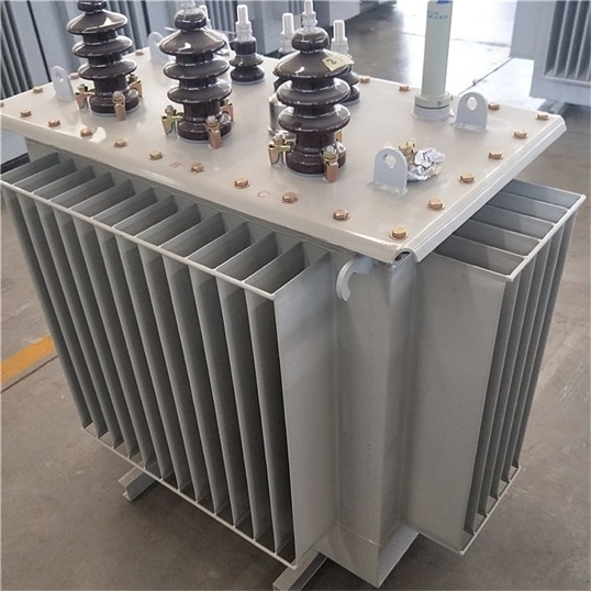
Typical Case Study
The SBH15-M series amorphous alloy transformer utilizes copper foil windings for the low-voltage side, achieving a no-load loss reduction of over 75% and a load loss reduction of 10%–15% compared to S11-type transformers.
3. Active Part Assembly Techniques
Assembly must address the sensitivity of amorphous alloy materials to mechanical stress:
Core Suspension Design
The lower yoke of the core adopts a detachable structure, leaving the core in a suspended state after assembly to prevent pressure-induced loss increases.
Dedicated tilting tables are used during active part flipping to avoid collisions and deformation.
Innovative Clamping Structure
Insulating plates are installed on both sides and the top/bottom of the yoke, as well as on both sides of the side limbs, with external steel plate clamps for protection.
Clamps must serve both clamping and protective functions to prevent core lamination fractures or debris generation.
Cleanliness Control
Metal fragments and dust are removed using vacuum cleaners before assembly, with joint areas sealed with insulating varnish.
Clean cloth or insulating paper is used to cover windings during operations to prevent core powder from entering the turns.
Data Support
European power sector trials indicate that amorphous transformers exhibit noise levels 6–8 dB higher than silicon steel transformers, though still compliant with environmental regulations.
4. Insulation Treatment Processes
Insulation design must balance cost-effectiveness and reliability:
Coil Insulation
High- and low-voltage coil end insulation uses 0.5–1.0 mm paperboard strips to reduce radial allowances.
Heating and shaping are followed by adhesive paper application to maintain coil dimensional stability.
Overall Insulation
The oil tank employs a fully sealed structure to extend service life and eliminate maintenance requirements.
Vacuum oil filling removes air bubbles from coils, ensuring stable insulation performance.
Standard Compliance
Conforms to GB1094 Power Transformers and JB/T10318-2002 Technical Parameters and Requirements for Oil-Immersed Amorphous Alloy Core Distribution Transformers.
5. Technical Challenges and Solutions
Material Cutting and Processing
Amorphous alloy ribbon is hard and brittle, necessitating specialized cutting tools and equipment to minimize cutting volume and reduce losses.
Magnetic Flux Density Optimization
Asymmetric magnetic flux distribution in four-frame five-limb wound cores during excitation may cause localized saturation, requiring magnetic circuit design optimization through simulation.
Noise Control
The magnetostriction of amorphous alloy is approximately 10% higher than that of silicon steel, demanding noise reduction through optimized core clamping structures and magnetic flux density control.
Benefit Analysis
For a 400 kVA transformer, the amorphous alloy model achieves a no-load loss of 170 W, representing a 78.75% reduction compared to the S9 type (800 W). This translates to annual energy savings of approximately 5,256 kWh (based on 8,760 operating hours).

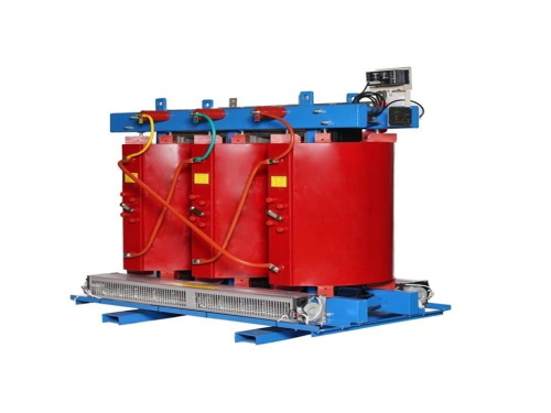
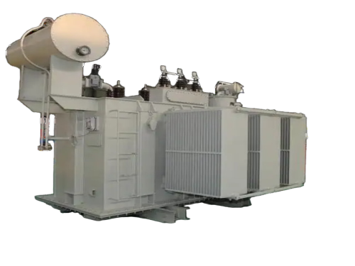
The main products include oil immersed transformers, dry-type transformers, power transformers, amorphous alloy transformers, mining transformers, box type substations, high and low voltage switchgear and supporting products
Add: South Head of Mount Huangshan Road, Liaocheng Development Zone, Shandong, China
Email:derun@drtransformer.com
Tel: +86 13706354419