
Inquiry

Project Review

Machining

Quality Control

Pass/Fail

Delivery
Regulations on the Grounded Operation of Mining Transformers
I. Core Principles
Neutral Point Ungrounded
Underground Distribution Transformers: It is strictly prohibited to directly ground the neutral point to prevent electric sparks caused by single-phase grounding faults, which could increase the risk of gas or coal dust explosions.
Surface Power Supply Restrictions: Transformers or generators with directly grounded neutral points on the surface shall not directly supply power to underground areas. If power supply is required, an isolation transformer (with a transformation ratio of 1:1) shall be used to change the neutral point grounding method to ungrounded, or neutral point grounding through a current-limiting resistor (with a fault current ≤ 200A) shall be adopted, and a two-stage neutral point zero-sequence current protection device shall be installed.

Construction of Protective Grounding Network
All metal enclosures, frameworks, armored cable steel strips (or wires), etc., of electrical equipment with a voltage ≥ 36V must be connected to the main grounding network through conductors to form a complete protective grounding system.
Requirements for the Main Grounding Network:
The main grounding electrodes shall be immersed in the water sumps, with one electrode placed in the main sump and one in the auxiliary sump. In multi-level mines, the main grounding network of each level shall be connected to the main and auxiliary sumps.
The main grounding electrodes shall be made of corrosion-resistant steel plates with an area ≥ 0.75m² and a thickness ≥ 5mm.
The resistance of the main grounding network measured from any local grounding device shall be ≤ 2Ω.
II. Specifications for Local Grounding Electrode Installation
Locations Where Installation is Mandatory
Each substation in the mining area (including mobile substations and mobile transformers).
Chambers equipped with electrical equipment and individual high-voltage equipment.
Low-voltage distribution points or locations with three or more pieces of electrical equipment.
At least one grounding electrode shall be installed in the machine lane and return airway of a coal mining face without a low-voltage distribution point.
Power armored cable connection boxes and transformer cable connection devices.
Installation Requirements
In Water Channels: Steel plates with an area ≥ 0.6m² and a thickness ≥ 3mm, or equivalent steel pipes, shall be placed flat at the bottom of the water channel.
At Other Locations:
Steel pipes with a diameter ≥ 35mm and a length ≥ 1.5m, with ≥ 20 holes with a diameter ≥ 5mm drilled in them, shall be vertically buried into the floor with a vertical burial depth ≥ 0.75m.
Alternatively, two steel pipes with a diameter ≥ 22mm and a length of 1m, each with 10 holes with a diameter ≥ 5mm drilled in them, shall be used. The two pipes shall be spaced ≥ 5m apart and buried vertically into the floor in parallel.
III. Standards for Grounding Wires and Connecting Conductors
Material and Cross-Sectional Area
Main Grounding Busbars: Bare copper wires with a cross-sectional area ≥ 50mm², galvanized iron wires with a cross-sectional area ≥ 100mm², or galvanized flat steel with a thickness ≥ 4mm and a cross-sectional area ≥ 100mm².
Auxiliary Grounding Busbars at Substation Distribution Points: Copper wires with a cross-sectional area ≥ 25mm², galvanized iron wires with a cross-sectional area ≥ 50mm², or galvanized flat steel with a thickness ≥ 4mm and a cross-sectional area ≥ 50mm².
Connecting Conductors: Bare copper wires with a cross-sectional area ≥ 25mm², galvanized iron wires with a cross-sectional area ≥ 50mm², or galvanized flat steel with a thickness ≥ 4mm and a cross-sectional area ≥ 50mm².
Equipment with a Rated Voltage ≤ 127V: Grounding conductors with a cross-sectional area ≥ 6mm² made of copper wire.
It is strictly prohibited to use aluminum conductors as grounding electrodes, busbars, or connecting wires.
Connection Requirements
Each piece of equipment shall be connected to the grounding network using an independent connecting conductor. Series grounding is prohibited.
The steel strips (or wires) of armored cables shall undergo regular anti-corrosion treatment (coated every 1-2 years).
The connection between the grounding busbar and the main grounding electrode shall be made by welding. If welding is not possible, it shall be tightened using galvanized bolts with a diameter ≥ 100mm.
IV. Specifications for Grounding of Special Equipment
Transformer Grounding
The steel strips or lead sheaths of the armored cables on the high- and low-voltage sides shall be connected to the dedicated grounding screws on the transformer enclosure through connecting conductors. For rubber-sheathed cables, the grounding core wire shall be connected to the grounding terminal inside the inlet and outlet device, and the grounding screw on the enclosure shall be connected to the grounding busbar.
Motor Grounding
The grounding screw on the enclosure shall be directly connected to the grounding busbar. For rubber-sheathed cables, the dedicated grounding core wire shall be connected to the grounding screw inside the connection box. For armored cables, the armored steel strip and lead sheath at the end of the cable shall be connected to the grounding screw on the enclosure.
High-Voltage Distribution Device Grounding
The grounded parts of the inlet and outlet cables shall be connected to the grounding screws on the distribution device using independent connecting wires. The grounding screw on the inlet cable head and the grounding screw on the base frame shall be connected and then connected to the grounding busbar.
Mobile Equipment Grounding
For mobile substations, the grounding core wires of the rubber-sheathed cables on the high- and low-voltage sides shall be connected to the grounding terminals inside the inlet devices. The grounding terminal outside the cable introduction device on the high-voltage side shall be firmly connected to the grounding screw on the high-voltage switch box. The grounding screws on the high- and low-voltage switch boxes and the dry-type transformer enclosures shall be respectively connected to the grounding busbar.
The grounding core wire of mobile electrical equipment shall be longer than the main core wire and connected to the grounding terminal inside the inlet device.
V. Maintenance and Inspection Requirements
Regular Inspections
Electrical Chambers with On-Duty Personnel: The grounding conditions shall be inspected once per shift.
Other Electrical Equipment: The grounding conditions shall be inspected at least once a week. Equipment that vibrates significantly or is frequently moved shall be inspected more frequently.
Main and Local Grounding Electrodes: A detailed inspection shall be conducted at least once a year. Problems such as poor contact or corrosion shall be checked when the electrodes are lifted out of the water. The main grounding electrodes in the main and auxiliary sumps shall not be lifted out simultaneously.
Grounding Resistance Testing
Main Grounding Network Resistance: The resistance shall be tested at least once per quarter and before newly installed equipment is put into operation.
Record Management: The test data shall be recorded in a table, and any problems found shall be reported and handled promptly.
Damage Repair
If a grounding device is damaged, it shall be repaired immediately. The equipment shall not be energized until the grounding device is repaired.
The mine's electrical and mechanical team and relevant teams shall strengthen inspections and immediately rectify any problems identified during group company or safety inspections.

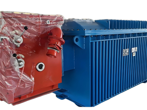
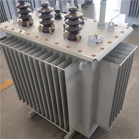
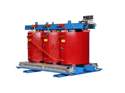
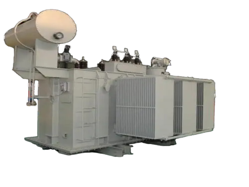
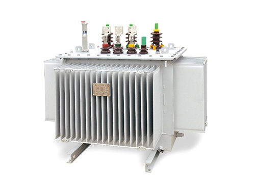
The main products include oil immersed transformers, dry-type transformers, power transformers, amorphous alloy transformers, mining transformers, box type substations, high and low voltage switchgear and supporting products
Add: South Head of Mount Huangshan Road, Liaocheng Development Zone, Shandong, China
Email:derun@drtransformer.com
Tel: +86 13706354419